3D Printing & Prototyping
Will Your Electronics Fit a 3D-Printed Enclosure?
A board can fit inside a drawing and still be awkward to install, connect or remove from the printed case. Before ordering a complete electronics enclosure, agree what must fit, how it will be assembled and what the first prototype needs to prove.
Section 01
Start with the exact hardware revision
Formlabs recommends measuring the board, mounting holes and accessible connectors when preparing an enclosure. Treat that as the starting point for a project brief, rather than relying on a product photograph.
Ask the person supplying the electronics to identify the board revision and the actual cables, fasteners and accessories that will be used. Put those references on one drawing or annotated photograph. If a dimension is estimated, mark it as unconfirmed instead of allowing it to look like an approved measurement.
Choose one reference corner for locating features. Record which side faces up and use the same units throughout. Ask who will confirm the measurements and provide the physical sample for the fit check.
Section 02
Separate planned clearance from print variation
Prusa explains that fitting printed parts requires testing: geometry, orientation, material and process settings affect the result. Its guidance does not establish one clearance that works for every assembly.
For this checklist, clearance means the intentional space between parts; dimensional tolerance means the permitted variation around a specified dimension. Ask the designer to state both where they matter. Saying only 'leave half a millimeter' does not tell the next person whether that means each side or the whole opening.
Here is a hypothetical arithmetic example, not a recommended manufacturing allowance: a 50.0 mm board with 0.5 mm nominal clearance on each side needs 51.0 mm of nominal internal width: 50.0 + 0.5 + 0.5. Adding two nominal 2.0 mm walls gives 55.0 mm outside. This simple example assumes straight walls and excludes ribs, fasteners and manufacturing variation; it does not prove that the printed assembly will fit.
Section 03
Check the plugged-in assembly
Formlabs highlights space for the cable housing around an opening, not just the connector on the board. Include the selected cable in the fit check.
Write the intended assembly sequence before approving the case: place the board, secure it, connect the cables and close the lid. Then try the reverse sequence. Can the person doing maintenance reach the fasteners and unplug the cable without removing unrelated parts? Record any step that needs a tool or a particular approach angle.
Decide how often the case should be opened. Ask the designer to justify the proposed closure for that use rather than choosing a snap-fit only because it looks cleaner.
Section 04
Use a small test piece to answer one question
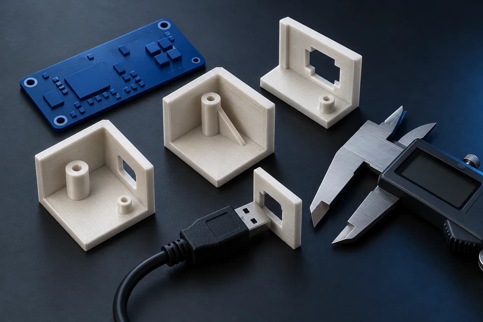
Our suggested first step is a limited fit sample when the uncertainty is local: a corner with a mounting post, a connector opening or a short section of the lid joint. Agree which question it answers before printing it.
Identify the sample and its settings. Note the measured opening, what fitted and what needed correction. A useful result might be 'the selected cable cannot be removed with the lid fitted,' followed by a drawing revision. A small sample does not approve the full case, its assembly sequence or its behavior in use.
Section 05
Inspect the printed edge before changing the drawing
For filament printing, Prusa documents how a first layer pressed against the print bed can become wider and interfere with a close fit. Its elephant-foot compensation addresses that first-layer effect; it is not a general correction for every dimensional problem.
If a trial part catches at one edge, record where contact occurs and ask whether the print or the drawing needs attention. Keep the original measurement and the correction in the review notes so the next prototype tests a stated change.
Section 06
Agree on a practical acceptance checklist
Use the following proposed checks for the complete prototype. Define any required force, number of opening cycles or measurement limits with the project team before testing:
- The identified board revision installs without forced bending.
- Mounting positions align and the intended tools can reach the fasteners.
- The selected cables can be inserted and removed in the agreed assembly state.
- The lid closes without trapping wires or pressing on components.
- The agreed maintenance sequence can be completed.
- Measurements, observations and drawing revisions are recorded.
- Remaining thermal, environmental and electrical requirements are listed separately.
Section 07
Send a fit brief with your enclosure request
Share the hardware references, available drawings, cable choices, intended environment and unresolved fit questions with Carras Technologies. The 3D printing and prototyping service can assess the scope and define an appropriate prototype.
Accepting dimensional fit is one decision. It does not establish waterproofing, electrical safety or readiness for an outdoor installation. Specify those needs separately so the project can include the appropriate design work and validation.